
More Heat
Fair warning: if you just want to use NTPsec to keep time on your LAN, then you can stop reading this blog post right now. On the other hand, if you are curious just how far one can push ntpd on a Raspberry Pi then you are in the right place. Bonus points if you duplicate this simple experiment. Everything was built with laboratory scrap, except for a $5 part.
Why?
In a previous post I showed how to improve the time and especially the frequency accuracy on a Raspberry Pi. The accuracies are well past that needed to serve local NTP time given the built-in 100 Mbps Ethernet port connected via USB 2.0 to the CPU.
So what is the point of super-charging what is essentially the VW Bug of the home computer world? One reason, as has been pointed out to me, is bragging rights: My RasPi is more accurate than yours!
But the main reason is to test the practical limits of the NTPsec code using a lab budget of $100, including a Raspberry Pi 3. Any motivated individual can, and some have, duplicate the described setup.
So far the core NTPsec code has held up well. There have been a few places where usable precision was being lost, and those have been fixed as they have been found.
How?
In that previous post the stabilization method was to stabilize the CPU temperature (ZONE0). The crystal on the RasPi is on the opposite side of the PCB, so only indirectly coupled with the CPU temperature.
This experiment will instead regulate the temperature of the environment surrounding the RasPi. The bare RasPi (no bubblewrap this time) is placed into a plain box and the box is covered in insulation. I used a plain plastic box covered in 1/4" thick Mylar/foam insulation.
The heat is added with a plain 120 Volt, 40 Watt incandescent bulb. A reclaimed 12V CPU fan blows air over the bulb to even out the temperature in the box. The bulb is turned on and off with a simple USB controlled relay. You can buy the relay on EBay for about $5, including shipping, assuming you are willing to wait for 3 weeks while the slow boat from China crawls to your door. Just search for 'USB relay 1 channel' and you will find many suppliers. A common one is the 'usbrelay1' with one relay. There are also models with two ('usbrelay2'), four ('usbelay4') and more relays.
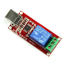
Even better than the price, the 'usbrelay1' presents itself as an HID device, just like your keyboard and mouse, so no matter what operating system you run you most likely already have the kernel driver installed.
As you would expect, the 'usbrelay1' comes with no documentation at all, but tools to control it are readily available. I used this command line tool written in a portable dialect of Python. It should run on just about any operating system. Installation instructions are in the package.
Each 'usbrelay1' is uniquely identified, to find the id of yours, simply run:
# usbrelay
Device Found
  type: 16c0 05df
  path: /dev/hidraw2
  serial_number:
  Manufacturer: www.dcttech.com
  Product:      USBRelay1
  Release:      100
  Interface:    0
  Number of Relays = 1
959BI_1=0
After that your relay is easy to control, to turn on:
# usbrelay 959BI_1=1To turn back off:
# usbrelay 959BI_1=0The last piece of hardware is a temperature sensor. Here we’ll use the TEMPer which was detailed in this previous blog post on ntplogtemp.
The Box
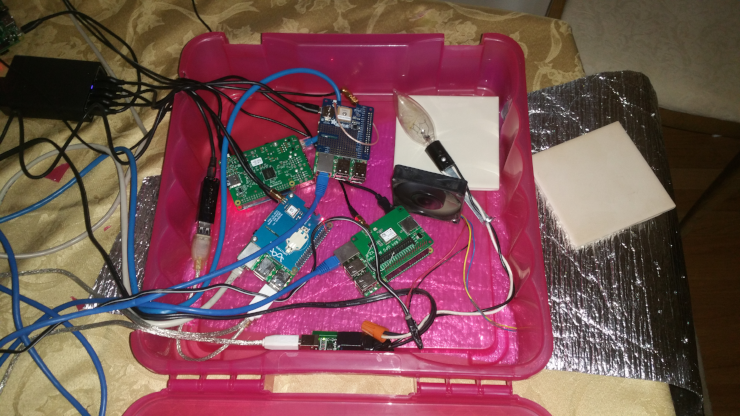
The test chamber is a plastic box that was sitting under a chair. Into the box go the Raspberry Pi’s, their wires exiting the box through two small holes on the left. The light bulb is placed on a ceramic tile in the upper right. The USB relay to control the bulb is on the bottom of the image.
The fan just below the light bulb is blowing for circulation. It helped even out the temperature in the box.
The extra tile on the right is placed over the light bulb before closing the box. I found that thermoplastic has a surprising tendency to melt when exposed to the bare bulb. The photo cleverly hides the Duck Tape on the bottom, top and right sides covering up holes.
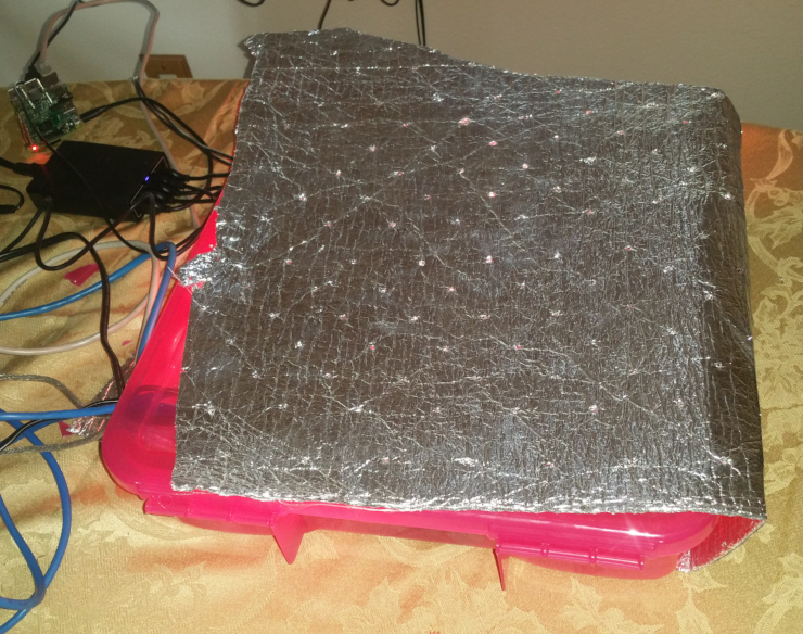
The closed up box is fairly airtight. The silver sheet is a Mylar coated thin foam insulation.
ntpheatusb
ntpheatusb is like ntpheat. They are both in the contrib/ directory and not installed on your system by default. But instead of making heat by exercising the CPU, it makes heat by switching the 40 Watt light bulb on and off with the 'usbrelay1'. The light is cycled once a minute to minimize relay wear.
The program implements a simple proportional controller and yields very good temperature stability. I got a Standard Deviation of 0.11 °C, approximately the granularity of the TEMPer itself. I tried a full PID controller, but the results were barely better and the tuning is burdensome.
Just note that a simple proportional controller will never stabilize at the set point. Just run the temperature controller at your desired set point for a while. Then restart it with the observed offset added in.
Running ntpheatusb is simple, to stabilize the temperature in the box at 45 °C:
# contrib/ntpheatusb -t 45After about an hour the box will stabilize at 44.4 °C, an undesired offset of 0.6 °C. Add in the offset and the box will stabilize at 45 °C after a while:
# contrib/ntpheatusb -t 45.6How Good?
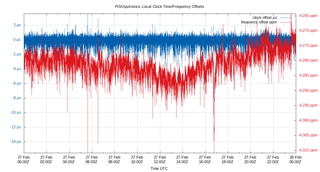
Check out the following plot of Time Offset and Frequency Offset. The Time Offset Standard Deviation of 469 nano seconds is a bit better than most thought possible. the Frequency Offset Standard Deviation of 4.2 ppb is about 120 times better than expected. Almost 5x better than using bubblewrap and ntpheat
| Min | 1% | 5% | 50% | 95% | 99% | Max | |
|---|---|---|---|---|---|---|---|
Local Clock Frequency Offset |
-4.3109 |
-4.2904 |
-4.287 |
-4.2801 |
-4.2733 |
-4.2708 |
-4.2643 |
Local Clock Time Offset |
-15.555 |
-1.919 |
-0.684 |
0.036 |
0.575 |
0.914 |
3.576 |
| 90% | 95% | StdDev | Mean | Units | |
|---|---|---|---|---|---|
Local Clock Frequency Offset |
0.0136 |
0.0196 |
0.0042 |
-4.2802 |
ppm |
Local Clock Time Offset |
1.259 |
2.833 |
0.4686 |
-0.0001 |
µs |
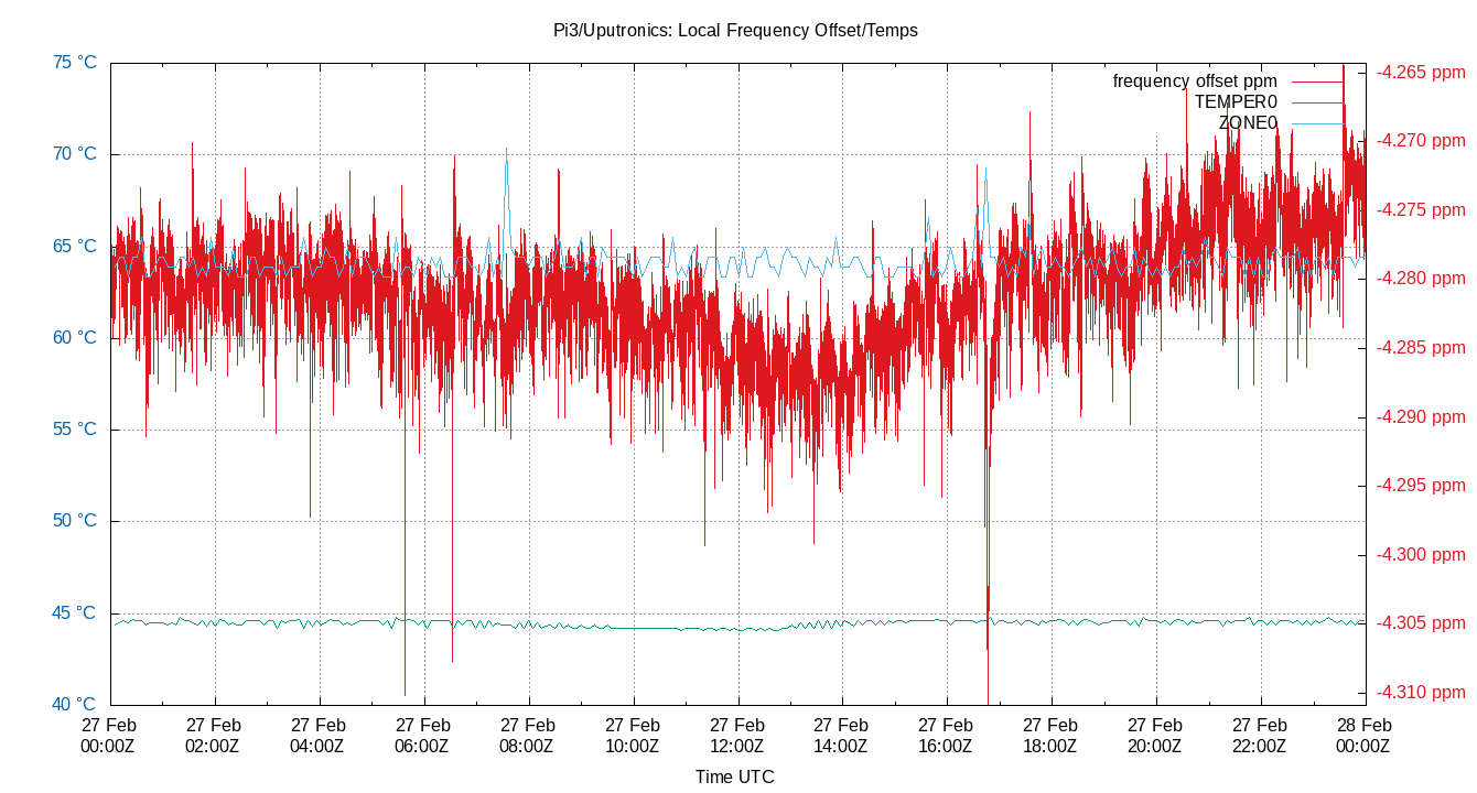
The plot of Local Clock Frequency Offset and ZONE0 and TEMPER0 shows that temperature has been mostly eliminated as a source of error. The ZONE0 spikes at about 07:30 and 16:30 do seem to loosely correlate with a frequency dips shortly after. That still leaves most of the jitter unexplained.
| Min | 1% | 5% | 50% | 95% | 99% | Max | |
|---|---|---|---|---|---|---|---|
Local Clock Frequency Offset |
-4.3109 |
-4.2904 |
-4.287 |
-4.2801 |
-4.2733 |
-4.2708 |
-4.2643 |
Temp TEMPER0 |
44.1 |
44.1 |
44.2 |
44.5 |
44.7 |
44.8 |
44.8 |
Temp ZONE0 |
63.376 |
63.376 |
63.376 |
63.914 |
65.528 |
67.142 |
70.369 |
| 90% | 95% | StdDev | Mean | Units | |
|---|---|---|---|---|---|
Local Clock Frequency Offset |
0.0136 |
0.0196 |
0.0042 |
-4.2802 |
ppm |
Temp TEMPER0 |
0.5 |
0.7 |
0.177 |
44.4593 |
°C |
Temp ZONE0 |
2.152 |
3.766 |
0.7861 |
64.1591 |
°C |
— Conclusions ==
The Standard Deviation of the box temperature is now just 0.177 °C. Pretty good considering the granularity of the TEMPer measurements is 0.1 °C. The crystal is now operating near its zero TC point and so the frequency is now relatively immune to the remaining temperature variation.
Sadly as the Frequency Stability gets better, the Time Offset and Jitter do not. Seeking better frequency stability by way of better temperature control does not appear to have any more big payoff over the previous bubblewrap experiment.
Next?
What are more possible experiments?
How to get better temperature stability?
Seek the exact best temperature for Zero TC. Maybe add auto-stepping to ntpheatusb?
Give up and find something that improves the time offset instead of the frequency offset?